M18 threaded mounted electromagnetic induction encoder


Description
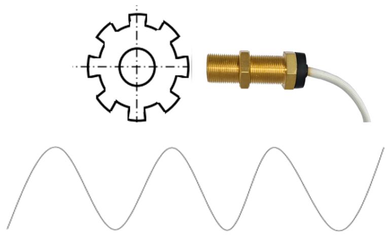
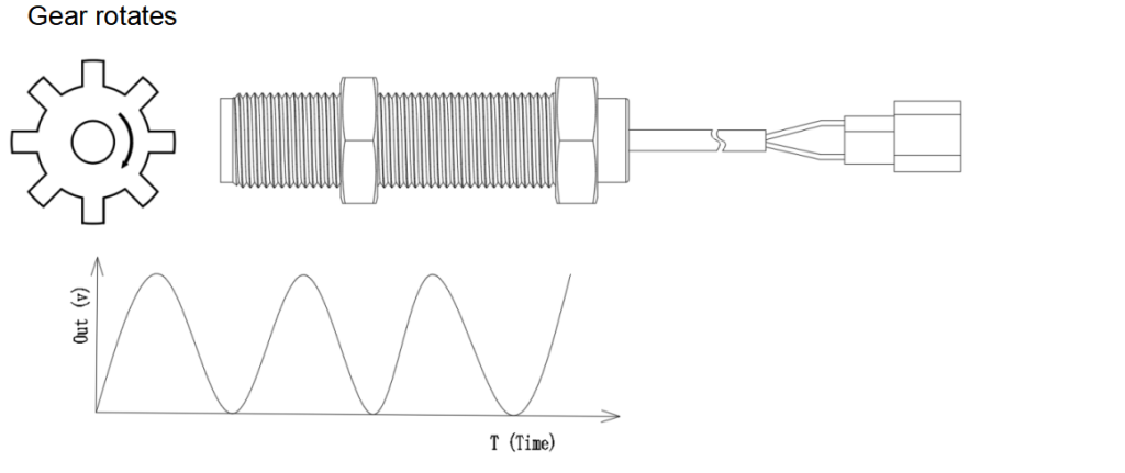
YH-M18-68-WS speed sensors are designed for sensing target’s rotational speed and position based on electromagnetic induction. A permanent magnet built in the rugged threaded package (brass) establishes a fixed magnetic field. When a ferrous metal target which is usually a gear wheel composed of Fe Co Ni materials(e.g. silicon steel ) approaches and passes near this passive sensor’s pole piece(sensing area),it will change the flux of the magnetic field and thus change its strength. A current is induced into a coil winding by alternation of magnetic field strength ,which will generate a complete sine wave pulse as output signal to a terminal.
VALUE TO CUSTOMERS
- Higher durability:
Wide operating temperature range enhances higher reliability
Passive device improve compatibility
IP69
Built in high-temperature magnet with strong stability
Electrical noise immunity protection for longer equipment uptime
- Optimized product structure(thread design), minimize service cost.
- High performance design redundancy, minimize issue of after sales service.
Features
- Wide operating temperature range: -50°C to 155°C (Brass)
- Easy installation, fixed position
- Environmental sealing: Moisture ingress protection rated to IP69K
- Strong electrical noise immunity, EMC EN IEC 61000-6-4:2019/EN IEC 61000-3-2:2019+A1:2021/EN 61000-6-2:2019
- Robust resistance to vibration: IEC60068-2-64-2019
- Wide working frequency range:0Hz-20KHz
- Sine wave output
Potential Application
- Measuring rotary speed of motors
- Measuring rotary speed of vehicle wheel
- Measuring displacement
- Measuring machine tool spindle speed
| ELECTRICAL SPECIFICATIONS | ||
| CHARACTERISTIC | CONDITION/COMMENT | PARAMETER |
| YH-M18-68-WS | ||
| Power type | / | Passive |
| Short Circuit Protection | ISO 16750-2 | 30V |
| Signal Type | Sine wave | Electromagnetic induction without external power supply |
| Sensing target | / | Ferrous material(Fe Co Ni) |
| Inter line resistance | 600±50ῼ | |
| Output amplitude | ≥2 V(p-p) (air gap 1.5mm) | |
| Working frequency | 0 Hz-30KHz (typical) ; 0 Hz-20K Hz(related to size of gears) | |
| Insulation Resistance | ISO 16750-2:2012 | >10 MOhm at 500 Vdc |
| MECHANICAL SPECIFICATIONS | |
| CHARACTERISTIC | PARAMETER |
| YH-M18-68-WS | |
| Air gap | 0.5mm-3mm |
| Connector model | DJ-7021-6.3-10 |
| Lead length | 450±20mm |
| Gear Type | Spur (ferrous) |
| Width of tooth tip | ≥2.54mm (recommended) |
| Gear thickness | ≥6mm |
| ENVIRONMENTAL SPECIFICATIONS | ||
| CHARACTERISTIC | CONDITION/COMMENT | PARAMETER |
| YH-M18-68-WS | ||
| EMC | EN IEC 61000-6-4:2019EN IEC 61000-3-2: 2019+A1:2021EN 61000-3-3:2013+A1:2019+2021EN IEC 61000-6-2:2019 | 10 kHz to 10 MHz, 60 m/V200 MHz to 2.7 GHz, 100 V/m800 kHz MHz to 1000 MHz, 3 m/V |
| Resistance to Vibration | IEC60068-2-64-2019 | 29.8 GRMS, 24 Hz to 2000 Hz, MIL-STD-202-214 |
| ESD | SAE J1113/13ISO 10605 | ±4 kV contact, ±8 kV air |
| Thermal shock cycle | -50°C to 155°C | 48 hours |
| Humidity | 95 %RH at 55°C | 10 %RH to 90 %RH at-40°C to 85°C,150 cycles, 600 hr total |
| Salt Fog | 5% salt solution by mass at 35°C and 93% RH for 400 hr, tested to 2000 hr with no ingress in the sensor packaging area | |
| Flame retardant grade | UL94-V-0 | The material stops burning within 10 seconds, and the residue after burning does not appear burning sparks or flames |
| Oil resistance grade | ASTM D471 | No issue when immersed in vehicle oil for a long time |
| Operating Temperature | -50°C-155°C | |
| Storage Temperature | -40°C-70°C | |
Principle
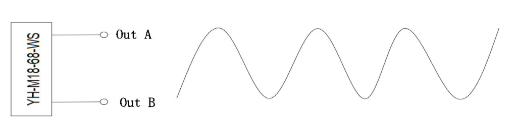
Connection
The output of the sensor is a passive self generating signal type sensor, which does not require an external power supply. Output A and B. Connect any pole to the GND pin of the signal processing terminal, and connect the other output pole to the signal input pin of the signal processing terminal.
Gear Size Recommended
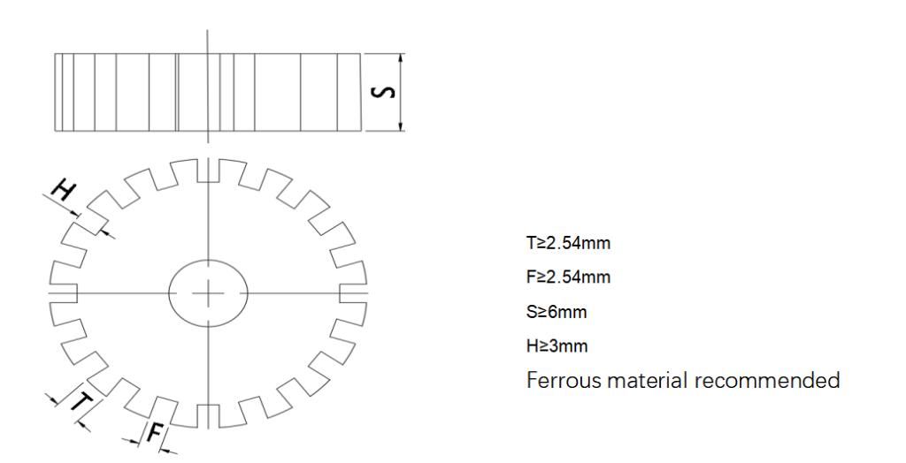
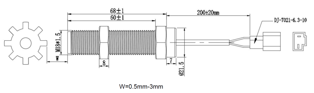
MOUNTING DIMENSIONS